What is UART?
UART stands for Universal Asynchronous Receiver/Transmitter. It’s basically a hardware communication protocol that acts like a translator between your computer (or microcontroller) and other serial devices. Think of it as the middleman that helps your system talk to things like GPS modules, modems, or even other microcontrollers — one bit at a time, over just a couple of wires.
Unlike protocols that rely on a shared clock, UART uses no clock signal between devices — that’s where the “asynchronous” part comes in. Instead, both devices just agree on a common speed (called the baud rate) and stick to it. This simplicity is why UART is still widely used in embedded systems and hardware hacking today.
How to Identify UART?
Identifying UART pins on a PCB might sound intimidating at first, but it’s actually pretty approachable once you know what to look for. One of the most reliable ways to do this is by using a Digital Multimeter (DMM). By measuring voltage levels and checking connectivity at various pinouts on a board, you can usually spot the UART interface.
Here’s the basic idea:
- You’re looking for four main signals — VCC, GND, TX (Transmit), and RX (Receive).
- The DMM helps you check voltage differences and continuity to pinpoint which pin is which.
- This process doesn’t require any prior access to firmware or a datasheet, making it especially useful for hardware hacking or reverse engineering projects.
We’ll break down this process step-by-step in the next section to help you confidently identify UART on almost any board.
Steps:
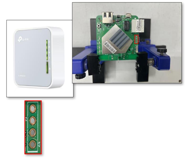
- Start by using the right tools to safely open up the TP-Link AC750 Mbps Wireless Portable Mini Travel Router (model TL-WR902AC).
- Once you’re in, take a good look at the Printed Circuit Board (PCB). You’ll want to visually inspect it for possible UART ports — these are usually a set of four (or more) pins grouped closely together.
- Employ a Digital Multimeter (DMM) to systematically test each pin for identification, beginning with Ground (GND), Voltage supply (Vcc), Transmit (Tx), and Receive (Rx).
- To confirm the presence of Ground (GND), follow the subsequent procedure. (Note: Hereafter, Ground will be referred to as GND.)
1. Use the continuity test function on your Digital Multimeter (DMM) to check for connectivity:

- Set the rotary switch of the multimeter to the continuity test mode.
- Select the option represented by the symbol ➤|‒ or •))).
- Locate a metallic sheet area or identify the Ground (GND) pin of the input DC supply.
- Position the red probe of the multimeter on the pin under test.
- Place the black probe of the multimeter on the metallic sheet or the GND of the input DC supply.
- If the multimeter shows a fairly constant voltage (like 3.3V), you’ve found VCC.
- If not, repeat the process with the other pins until you spot it.
2. To confirm the presence of VCC (Voltage Common Collector), follow the steps below:
Note: While VCC isn’t used when connecting to a serial interface, identifying it helps narrow down the search for Tx and Rx.
- Power on the device.
- Perform a multimeter voltage test:
- Set the multimeter’s rotary switch to V (20), assuming the voltage will be under 20V.
- Place the red probe on the pin you’re testing.
- Place the black probe on the previously identified GND pin or the GND of the input DC supply.

- If the multimeter shows a fairly constant voltage (like 3.3V), you’ve found VCC.
- If not, repeat the process with the other pins until you spot it.
3. To confirm the presence of the Transmit (Tx) pin, follow these steps:
- Power on the device and begin testing immediately.
- Set your multimeter to voltage mode (V).
- Place the red probe on the pin under test.
- Place the black probe on the known GND pin.
- If the voltage varies, you’re likely looking at the Tx pin.

- If it doesn't, move on and try other pins.
- If two pins consistently show 3.3V, one could be Tx and the other VCC. To confirm, power cycle the device and check both pins quickly after boot-up.
- If you're still uncertain, an oscilloscope can help clarify things.
4. To confirm the presence of the Receiver (Rx) pin, follow these steps:
- Identifying the Rx pin can be a little tricky since it doesn’t always have obvious characteristics.
- Start by powering on the device and quickly testing each pin with the multimeter.
- Set the multimeter to voltage mode (V) and place the red probe on the pin you’re checking.
- Place the black probe on the known GND pin.

- Sometimes the voltage on the Rx pin will stay steady—either low or high.
- Other times, it may fluctuate.
- In our experience, it often shows a constant low voltage.
- If it’s still unclear, keep testing other pins. And if you’ve already identified GND, VCC, and Tx out of four pins, then the one left is most likely Rx.
Before We Sign Off:
Identifying UART pins might seem a bit intimidating at first, but with a digital multimeter, a bit of patience, and a systematic approach, it becomes a surprisingly satisfying puzzle to solve. Whether you're exploring hardware for the first time or diving deeper into embedded device hacking, getting familiar with UART is a great foundation. In our next blog, we’ll move a step further—connecting to these pins and interacting with the device to (hopefully) get shell access. That’s where things start getting really interesting. here just change first line Until then, happy probing—and remember, always double-check your connections before plugging anything in!
