Before diving in, make sure you have a target device with accessible JTAG pins—this could be a development board, a router, or any embedded device you're comfortable experimenting with.
So you've got your JTAGulator and a target device ready. Now it's time to connect them together properly. The process is simple
1
Power Target Separately
The JTAGulator doesn't provide power to the device you're trying to test. So make sure your target board is already powered through USB, battery, or its regular power adapter.
Don't try powering the board from the JTAGulator—it's not meant for that.
Before making any connections, make sure your target system is powered off. This helps avoid any accidental shorts or damage.
2
Connect GND First
Connect one of the GND pins from the JTAGulator to the ground pin on your target board. A common ground is necessary for stable communication.
Identify GND Pins (Continuity Mode)
Set your multimeter to continuity mode (diode symbol with sound).
- Touch the black probe to a known ground point, like metal casing of a USB port or a large ground pad.
- Use the red probe to test all pins in the suspected header.
- Any pin that beeps or reads near 0 ohms is likely GND.
3
Attach JTAGulator I/O Pins
JTAGulator has 24 labeled I/O pins (IO0 to IO23). These are the pins you'll use to connect to the unknown header or test points on your target.
- Use jumper wires to connect some of these IO pins to the suspected JTAG pins on your target.
- You don't need to use all 24—usually, 4 to 6 connections is enough for JTAG.
- It's okay if you don't know which target pin is TCK, TDI, etc. That's the whole point—the JTAGulator will figure it out for you.
4
Avoid Connecting GND to I/O Pins
When selecting channels during a scan, make sure none of the JTAGulator's I/O pins are connected to a ground pin on the target device. Doing so can interfere with the scanning process or lead to inaccurate results.
5
Power On Target Device
Once everything is connected, you can power on your target device. Now the JTAGulator is ready to scan and detect any valid JTAG connections.
6
Connect JTAGulator to Your Computer
Plug the JTAGulator into your computer using a USB cable. It should show up as a serial device (e.g., /dev/ttyUSB0 on Linux).
Use Picocom or PuTTY for Serial Communication
To interact with the JTAGulator once it’s connected, you can use serial communication tools like Picocom (Linux/macOS) or PuTTY.
Since we’re using Picocom here, open a terminal and run the following command to start the session:
Connection Command:
sudo picocom -b 115200 /dev/ttyUSB0
This sets the baud rate to 115200 and opens the USB device port. Once connected, you’ll be able to send commands to the JTAGulator and see the output in real time.
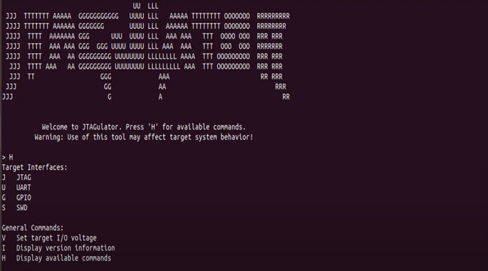
Once you're connected to the JTAGulator using a serial console tool like Picocom, you'll see a simple terminal window waiting for your input. The first thing you'll want to do is type h this displays a help menu listing all the available commands you can run.